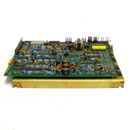
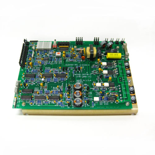
GA370-3 Glentek Servo Amplifier Drive
$3,142.86
Glentek GA370-3 high-bandwidth, Torque-Width Series PWM servo amplifier card is engineered for high-precision velocity and torque control of permanent magnet DC (PMDC) servo motors.
In stock
Description
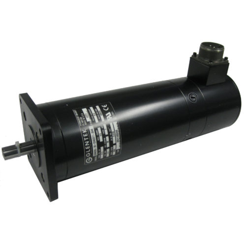
Glentek GA370-3 is a single high power, high bandwidth modular Pulse-Width-Modulated (PWM) servo amplifier from Glentek’s Torque-Switch series, designed specifically for use with Glentek GM4050 DC permanent magnet servo motors. It is widely used in industrial CNC machinery, such as those with Anilam, Fagor, or Milltronics controls.
Note: This product is a brand-new, original Glentek amplifier drive board, not from old stock. We have these in stock and ready to ship now.
Interchangeability & Retrofit Guide
- Direct Drop-In Replacement: The GA370-3 is a known industry-standard replacement for the legacy Servo Dynamics SDFPO(S)1525-17 amplifier drive axis card. If you are unsure of your requirements, please reach out to us for technical support.
- Motor Interoperability: Optimized natively for Glentek GM4050 permanent magnet DC brush servo motors. It can be paired with third-party brush servo motors provided the electrical specifications and tachometer voltage gradients align with the drive’s threshold limits.
Additional information
| Condition | New |
|---|---|
| Part Number (MPN) | GA370-3 |
| Manufacturer | Glentek |
Frequently Asked Questions
Yes, the GA370-3 is a universal pulse-width-modulated analog brush servo amplifier. While tuned out of the box for Glentek GM4050 series motors, it can drive third-party permanent magnet DC brush motors. You must verify that the motor’s voltage, peak/continuous current draw, and analog tachometer feedback scaling (+/- 90V maximum input) do not exceed the drive’s listed hardware constraints.
An ECB fault is a latched condition caused by an over-current event (either low-speed or high-speed overload). First, isolate power from the machine and check the motor leads for phase-to-phase or phase-to-ground short circuits. Inspect the machine’s axis for mechanical binding or physical blockages. Once the fault condition is addressed, cycle the logic power or use the hardware Reset pin connection to clear the latched state.
Velocity loop tuning is managed via hardware potentiometers mounted directly on the card faceplate. Adjustments include Signal Gain, Tachometer Gain, and Compensation. Tuning requires monitoring the tachometer feedback response with an oscilloscope under standard operational loop loads. This allows you to eliminate low-speed hunting or axis overshoot while maximizing response bandwidth.